
here we talk about the detail step by step guide of the emitter coupled logic.first get deyal about it we need to the get some basic knowledge about the electronics switching devices.
what is electronics switch ?
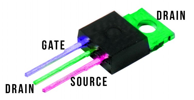
In hardware, an electronic switch is an electronic part that can switch an electrical circuit, intruding on the present it starting with one channel then onto the next.
Regularly, electronic switches utilize strong state gadgets, for example, transistors, however vacuum tubes can be utilized also in high voltage applications.
other some of like MOSFET ,FET ,IGBT ans many more etc..
basic of emitter coupled logic
In electronics, emitter-coupled logic (ECL) is a high-speed integrated circuit bipolar transistor logic family.
ECL uses an overdriven BJT differential amplifier with single-ended input and limited emitter current to avoid the saturated (fully on) region of operation and its slow turn-off behavior.
As the current is steered between two legs of an emitter-coupled pair, ECL is sometimes called current-steering logic (CSL),current-mode logic (CML) or current-switch emitter-follower (CSEF) logic.
In ECL, the transistors are never in saturation, the input/output voltages have a small swing (0.8 V), the input impedance is high and the output resistance is low; as a result, the transistors change states quickly, gate delays are low, and the fanout capability is high.
In addition, the essentially-constant current draw of the differential amplifiers minimises delays and glitches due to supply-line inductance and capacitance, and the complementary outputs decrease the propagation time of the whole circuit by reducing inverter count.
Principle of emitter coupled logic
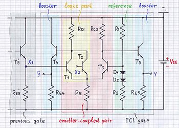
ECL is devised which is based on the emitter coupled pair.For The Detail Shown in the above figure.here emitter is common connection..
in this figure all transistor , register and some diode connection is provided.
Shown in figure that left half of the pair which has two parallel-connected input transistors T1 and T2.And Input NOR Logic is used.
Shown on figure that on the right T1 And T2 Transistor T3 is provided which based voltage is fixed by a reference voltage source.
In shaded light green voltage divider with diode thermal compensation (R1,R2 and D1,D2) And also buffering emitter follower.
Emitter voltage is kept relatively steady.Re is the common emitter resistance which work like current source.
feature and advantage of emitter coupled logic
Emitter coupled logic is fastest switching devices.
Here emitter is BJT connected in both the terminal.
this device is never be saturated.storage delay of ECL is eliminated.
its propagation delay is minimum so its speed is too much high.
it has low output impedance and high input impedance.
Fan out is around 25 that means our ECL logic circuit can try total 25 similar logic gates.
Disadvantage of emitter coupled logic
Its logic levels are close to each other so its not suitable for the heavy industries.
its required large value of the silicon quantity so its soo much costly.
its has heavy power dissipation..
due to this I2R drop is too much high.
i hope this guide is helpful for you..if any problem then contact with us..
for more detail shown in below video
